Beetle |
您所在的位置:网站首页 › page c3 › Beetle |
Beetle
|
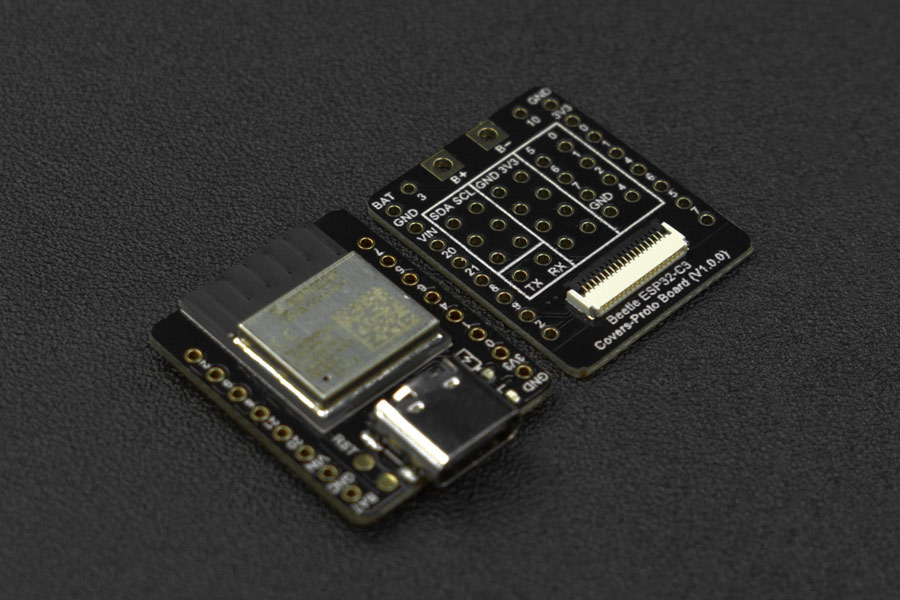
Beetle ESP32-C3, mainly intended for IoT applications, is a controller based on ESP32-C3 RISC-V 32bit single-core processor. On a coin-size board of 25*20.5 mm, there are up to 13 IO ports broken out, so you don't have to worry about running out of IO ports when making projects. Meanwhile, li-ion battery charging management function is integrated on the board which allows to directly connect li-ion battery without extra modules, while ensuring the application size and safety. The equipped expansion board for Beetle ESP32-C3 brings out more power sources without increasing product volume, more convenient to solder. Besides, the onboard easy-to-connect GDI saves the trouble of wiring when using a screen. Beetle ESP32-C3 supports WiFi and Bluetooth 5(LE) dual-mode communication that reduces the difficulty of networking, and also both Bluetooth Mesh protocol and Espressif WiFi Mesh are supported for more stable communication and a larger coverage area. Detailed tutorials for Beetle ESP32-C3 are provided for users to use the controller’s WiFi function, such as connecting to IoT platforms like Aliyun, or IFTTT, etc. Or users can use various sensors and actuators from DFRobot to build up IoT systems. Beetle ESP32-C3 can be programmed by Arduino IDE, ESP-IDF, MicroPython, C and Python are both supported. If the serial port keeps connecting and then disconnecting repeatedly, please connect pin 9 to GND and power on again. V2.0.0 Modification: BOOT (IO9) and RST buttons are added for entering download boot mode and reset more easily. 2. Features Ultra-small size, the size is only 25×20.5mm(0.98×0.81 inch) Onboard lithium battery charging management, charging and discharging is safer The matching bottom plate makes it more convenient to make projects and use the screen RISC-V 32-bit core Supports Wi-Fi and Bluetooth 5 (LE) dual-mode communication 3. Specification
Basic parameters Operating voltage: 3.3V Type-C input voltage: 5V DC VIN input voltage: 5V DC Working current: 25mA Maximum charging current: 400mA Working temperature: -40~105℃ Module size: 25x20.5 mm(0.98*0.81 inch)Hardware information Processor: 32-bit RISC-V single-core processor Main frequency: 160 MHz SRAM: 400KB ROM: 384KB Flash: 4MB RTC SRAM: 8KB Clock: External (32 kHz) crystal, built-in fast RC oscillator clock 17.5 MHz (adjustable), and PLL clock USB: USB 2.0 up to 12Mbit/sWIFI WIFI protocol: IEEE 802.11b/g/n WIFI bandwidth: 2.4 GHz band supports 20 MHz and 40 MHz bandwidth WIFI mode: Station mode, SoftAP mode, SoftAP+Station mode and promiscuous mode WIFI frequency: 2.4GHz Frame Aggregation: TX/RX A-MPDU, TX/RX A-MSDUBluetooth Bluetooth protocol: Bluetooth 5, Bluetooth mesh Bluetooth frequency: 125 Kbps, 500 Kbps, 1 Mbps, 2 MbpsInterface pins Digital I/O x13 LED PWM controller with 6 channels SPI x1 UART x2 I2C x1 I2S x1 Infrared receiver and transmitter: transmit channel x2, receive channel x2, (any pin) 2 × 12-bit SAR A/D converters, 6 channels DMA controller, 3 receive channels and 3 transmit channels 4. Schematic diagram of functional pins Function Instructions
 Pin Overview
GPIO: regular pins
Analog Port: Analog Input Pin
JTAG: Debug Interface
ADC: analog-to-digital conversion
VIN: 5V power input
BAT: battery access port
GDI display interface
Pin Overview
GPIO: regular pins
Analog Port: Analog Input Pin
JTAG: Debug Interface
ADC: analog-to-digital conversion
VIN: 5V power input
BAT: battery access port
GDI display interface

This interface is a DFRbot dedicated GDI display interface for connecting a screen using a 18pin-FPC wire. The pin list for using GDI camera interface is shown below: FPC PINS Beetle ESP32 C3 Pins Description VCC 3V3 3.3V BLK (PWM dimming) 10 Backlight GND GND GND SCLK 4/SCK SPI clock MOSI 6/MOSI Host output, slave input MISO 5/MISO Host input, slave output DC 1 Data/command RES 2 Reset CS 7 TFT Chip Select SDCS 0 SD card chip select FCS NC Font library TCS 3 Touch SCL 22/SCL I2C clock SDA 21/SDA I2C data INT NC INT BUSY-TE NC ripstop pins X1 NC custom pin 1 X2 NC custom pin 2When using FPC to connect the screen, please configure the corresponding pin numbers according to the GDL demo. Normally, only three pins need to be configured on different main controllers. Displays that support GDI: 1.54" 240x240 IPS wide viewing angle TFT display 1.8" 128x160 IPS TFT LCD Display 2.0" 320x240 IPS wide viewing angle TFT display 2.8" 320x240 IPS TFT resistive touch display 3.5" 480x320 IPS TFT capacitive touch display 1.51" OLED Transparent Display with Converter 5. The first time to use 5.1 Arduino Environment ConfigIf you use Beetle-ESP32-C3 for the first time, you need to know the following steps Add the json link in the IDE Download the core of the MCU Select the development board and serial port Open the sample code and burn it Get to know the serial monitorArduino IDE compiler environment config Configure URL to the Arduino IDE Open Arduino IDE and click File->Preferences, as shown below. 
In the newly opened interface, click the button in the red circle as shown below
Copy the following link into the new pop-up dialog box:https://raw.githubusercontent.com/espressif/arduino-esp32/gh-pages/package_esp32_index.json Note: If you have installed another environment before, you can press Enter key at the beginning or end of the previous link and paste the link into any line.
Click OK Update the board Open Tools->Board:->Boards Manager... as shown below:
Boards Manager will automatically update the boards as shown below:
After completing the update, you can enter esp32 at the top, select esp32 and click install when the following occurs (current version is 2.0.0):
Wait for the end of the following progress bar:
After completing the installation, the list will show that the esp32 has been installed, as shown below:
Click Tools->Board: select ESP32C3 Dev Module (usually the first in the list)
Click Port to select the corresponding serial port(If the serial port keeps connecting and then disconnecting repeatedly, please connect pin 9 to GND and power on again.)
Onboard LED is default to pin 10 Code int led = 10; void setup() { pinMode(led,OUTPUT); } void loop() { digitalWrite(led,HIGH); delay(1000); digitalWrite(led,LOW); delay(1000); } Paste the above program into the program box Click the arrow to wait for the program to be compiled and burn it to the development board Burn succeeded
ledcAttachPin(GPIO, Channel) Description: specify which GPIO the signal will appear on Parameter: GPIO: GPIO to output the signal Channel: GPIO where the signal will be generatedledcWrite(Channel, dutyCycle) Description: set the PWM signal generation channel Parameter: Channel: signal generation channel dutyCycle: PWM valueledcSetup(Channel, freq, resolution) Description: set the PWM signal generation channel Parameter: LedChannel: signal generation channel freq: PWM frequency resolution: PWM resolution SampleThe ESPC3 PWM can be freely mapped to other ports for output, you need to set it up. This sample will be used to help you understand the operation steps, and you can see the LED gradually brighten and dim through it. /* * LED breathing light sample */ const int ledPin = 10; // Actually output pin after PWM generation //Set PWM parameter const int freq = 5000;//PWM frequency const int ledChannel = 0;//GPIO for signal generation const int resolution = 8;//8-bit resolution void setup(){ //PWM parameter setting ledcSetup(ledChannel, freq, resolution); //Attach the signal generation channel to the output channel ledcAttachPin(ledPin, ledChannel); } void loop(){ //Start to brighten for(int dutyCycle = 0; dutyCycle = 0; dutyCycle--){ // changing the LED brightness with PWM ledcWrite(ledChannel, dutyCycle); delay(15); } }6.2 Interrupt ESP32C3 interrupts can be freely assignedpinMode(GPIO,INPUT_PULLUP); Description: external interrupt pin definition Parameters: GPIO: the pin that ESP32C3 is to use as an interrupt. INPUT_PULLINGUP: set pull-up mode.attachInterrupt(digitalPinToInterrupt(pin), ISR, mode) Description: External interrupts Parameters: pin: the Arduino pin number. ISR: the ISR to call when the interrupt occurs; this function must take no parameters and return nothing. This function is sometimes referred to as an interrupt service routine. mode: defines when the interrupt should be triggered. Three constants are predefined as valid values. CHANGE trigger the interrupt pin when the pin level changes RISING trigger the interrupt pin when the pin level changes from low to high FALLING Trigger the interrupt pin when the pin level changes from high to lowdetachInterrupt(digitalPinToInterrupt(pin)) Description: Turn off the given interrupt. Parameters: pin: the interrupt pin to be disabledInterrupts () Description: Re-enables interrupts (after they've been disabled by noInterrupts(). Interrupts allow certain important tasks to happen in the background and are enabled by default. Some functions will not work while interrupts are disabled, and incoming communication may be ignored. Interrupts can slightly disrupt the timing of code, however, and may be disabled for particularly critical sections of code. noInterrupts () Description: Disables interrupts (you can re-enable them with interrupts()). Interrupts allow certain important tasks to happen in the background and are enabled by default. Some functions will not work while interrupts are disabled, and incoming communication may be ignored. Interrupts can slightly disrupt the timing of code, however, and may be disabled for particularly critical sections of code. 6.3 Setial Port ESP32C3 serial port initialization requires mapping Serial1.begin(baud, config, rxPin, txPin); Description: Serial1 initialization Parameters: baud: baud rate config: data bit and stop bit setting rxPin: RX pin txPin: TX pin Serial1.begin(9600,SERIAL_8N1,/*rx =*/0,/*Tx =*/1); 6.4 ServoESP32-C3 doesn't support driving servo through the Servo library. Please search and install the ESP32_ISR_Servo library in Sketch->Include Library->Manage Library to drive servo. 7. Advanced Tutorial 7.1 Use SD Library SD Classbegin(cspin) Description: Initializes the SD library and card. This begins use of the SPI bus (digital pins 11, 12, and 13 on most Arduino boards; 50, 51, and 52 on the Mega) and the chip select pin, which defaults to the hardware SS pin (pin 10 on most Arduino boards, 53 on the Mega). Note that even if you use a different chip select pin, the hardware SS pin must be kept as an output or the SD library functions will not work. Parameter: cspin:the Arduino pin connected to the chip select line of the SD card.Return: boolean type. True on success; false on failure exists() Description: Test whether a file or directory exists on the SD card. Syntax: SD. exists( filename) Parameter: filename: the name of the file to test for existence, which can include directories (delimited by forward-slashes, /)Return: boolean type, true if the file or directory exists, false if not open()Description: Opens a file on the SD card. If the file is opened for writing, it will be created if it doesn't already exist (but the directory containing it must already exist). Syntax: SD.open( filename) SD.open(filename,mode) Parameter: filename: the name the file to open, which can include directories (delimited by forward slashes, /) mode (optional): the mode in which to open the file, defaults to FILE_READ - byte. one of: FILE_READ: open the file for reading; FILE_WRITE: open the file for reading and writing.Return: a File object referring to the opened file: if the file couldn't be opened, this object will evaluate to false in a boolean FILE_WRITE: open the file for reading and writing. Return: a File object referring to the opened file;Return false if the file cannot be opened. remove() Description: Remove a file from the SD card. If the file didn't exist, the return value is unspecified, so it is better to use SD. Exists (file name) to detect whether the file exists before removing the file. Syntax: SD. remove( filename) Parameter: filename:the name of the file to remove, which can include directories (delimited by forward-slashes, /)Return: boolean type. True if the removal of the file succeeded, false if not. mkdir(filename) Description: Create a directory on the SD card. Parameter: filename: the name of the directory to create, with sub-directories separated by forward-slashes, /Return: boolean type. True if the creation of the directory succeeded, false if not. rmdir(filename) Description: Remove a directory from the SD card. The directory must be empty. Syntax: SD.rmdir( filename) Parameter: filename: the name of the directory to remove, with sub-directories separated by forward-slashes, /Return: booleantype. True if the removal of the directory succeeded, false if not. File ClassThe file class provides the function of reading/writing files. The function of this class is very similar to the that of serial port related functions used before. The member functions are as follows. available()Description: Check if there are any bytes available for reading from the file. Syntax: file. available()Parameter: file:an instance of the File classReturn: the number of bytes available close()Description: Close the file, and ensure that any data written to it is physically saved to the SD card. Syntax: file. close()Parameter: file:an instance of the File classReturn: none flush()Description: Ensures that any bytes written to the file are physically saved to the SD card. This is done automatically when the file is closed. Syntax: file.flushParameter: file: an instance of the File classReturn: none peek() Description: Read a byte from the file without advancing to the next one. Parameter: file: an instance of the File classReturn: The next byte (or character), or -1 if none is available. position( )Description: Get the current position within the file (i.e. the location to which the next byte will be read from or written to). Syntax: file. position()Parameter: file: an instance of the File classReturn: the position within the file print()Description: Print data to the file, which must have been opened for writing. Syntax: file. print(data)file. print(data,BASE)Parameter: file: an instance of the File class data:the data to print (char, byte, int, long, or string) BASE(optional): the base in which to print numbers: BIN for binary (base 2), DEC for decimal (base 10), OCT for octal (base 8), HEX for hexadecimal (base 16).Return: byte number to be transmitted. println()Description: Print data, followed by a carriage return and newline, to the File, which must have been opened for writing. Syntax: file. println(data)file,println(data,BASE)Parameter: file:an instance of the File class data (optional): the data to print (char, byte, int, long, or string) BASE (optional): the base in which to print numbers: BIN for binary (base 2), DEC for decimal (base 10), OCT for octal (base 8), HEX for hexadecimal (base 16).Return: byte number to be transmitted. seek()Description: Seek to a new position in the file, which must be between 0 and the size of the file (inclusive). Syntax: file. seek( pos)Parameter: file:an instance of the File class pos: the position to which to seekReturn: true for success, false for failure (boolean) size()Description: Get the size of the file. Syntax: filue. size()Parameter: file:an instance of the File classReturn: the size of the file in bytes read()Description:Read from the file. Syntax: file.read Parameter: file:an instance of the File classReturn: The next byte (or character), or -1 if none is available. write()Description: Write data to the file. Syntax: file. write(data)file. write(buf,len) Parameter: file:an instance of the File class data:the byte, char, or string (char*) to write buf: an array of characters or bytes len:the number of elements in bufReturn: the number of bytes written isDirectory()Description: Reports if the current file is a directory or not Syntax: file.isDirectory()Parameter: file: an instance of the File classReturn:boolean. True if the file is a directory, false if not openNextFile()Description: Reports the next file or folder in a directory. Syntax: file.openNextFile()Parameter: file: an instance of the File class that is a directoryReturn: the next file or folder in the path rewindDirectory()Description: Back to the first file in the directory Syntax: file.rewindDirectory()Parameter: file: an instance of the File class.Return: None 7.2 ESP32-C3 Bluetooth Receive and Transmit 7.2.1 ESP32-C3 and mobile phone Bluetooth communicationThis example demonstrates the data transmission between ESP32-C3 and the mobile phone. If you need to modify or use the data, you only need to change the data receiving part or the data transmitting part of the code. /* Video: https://www.youtube.com/watch?v=oCMOYS71NIU Based on Neil Kolban example for IDF: https://github.com/nkolban/esp32-snippets/blob/master/cpp_utils/tests/BLE%20Tests/SampleNotify.cpp Ported to Arduino ESP32 by Evandro Copercini Create a BLE server that, once we receive a connection, will send periodic notifications. The service advertises itself as: 6E400001-B5A3-F393-E0A9-E50E24DCCA9E Has a characteristic of: 6E400002-B5A3-F393-E0A9-E50E24DCCA9E - used for receiving data with "WRITE" Has a characteristic of: 6E400003-B5A3-F393-E0A9-E50E24DCCA9E - used to send data with "NOTIFY" The design of creating the BLE server is: 1. Create a BLE Server 2. Create a BLE Service 3. Create a BLE Characteristic on the Service 4. Create a BLE Descriptor on the characteristic 5. Start the service. 6. Start advertising. */ /* This example demonstrates the transparent transmission of bluetooth data, burning the code, opening the serial monitor, and opening the BLE debugging assistant of the mobile phone * 1. You can see the data sent by ESP32-C3--see APP usage diagram * 2. Data can be sent to ESP32-C3 through the input box of the BLE debugging assistant--see APP usage diagram * This example is changed from the BLE_uart example */ #include #include #include #include BLEServer *pServer = NULL; BLECharacteristic * pTxCharacteristic; bool deviceConnected = false; uint8_t txValue = 0; // See the following for generating UUIDs: // https://www.uuidgenerator.net/ #define SERVICE_UUID "6E400001-B5A3-F393-E0A9-E50E24DCCA9E" // UART service UUID #define CHARACTERISTIC_UUID_RX "6E400002-B5A3-F393-E0A9-E50E24DCCA9E" #define CHARACTERISTIC_UUID_TX "6E400003-B5A3-F393-E0A9-E50E24DCCA9E" //Bluetooth connect/disconnect processing. Triggered automatically when a connect/disconnect event occurs class MyServerCallbacks: public BLEServerCallbacks { void onConnect(BLEServer* pServer) { //This function will be executed when Bluetooth is connected Serial.println("Bluetooth connected"); deviceConnected = true; }; void onDisconnect(BLEServer* pServer) { //This function will be executed when Bluetooth is disconnected Serial.println("Bluetooth disconnected"); deviceConnected = false; delay(500); // give the bluetooth stack the chance to get things ready pServer->startAdvertising(); // restart advertising } }; /****************Data receiving section*************/ /****************************************/ //Bluetooth receive data processing. Triggered automatically when data is received class MyCallbacks: public BLECharacteristicCallbacks { void onWrite(BLECharacteristic *pCharacteristic) { std::string rxValue = pCharacteristic->getValue();//Receive data and assign it to rxValue //if(rxValue == "ON"){Serial.println("开灯");} //Determine whether the received character is "ON" if (rxValue.length() > 0) { Serial.println("*********"); Serial.print("Received Value: "); for (int i = 0; i < rxValue.length(); i++){ Serial.print(rxValue[i]); } Serial.println(); Serial.println("*********"); } } }; /***************************************/ /****************************************/ void setup() { Serial.begin(115200); BLEBegin(); //Initialize Bluetooth } void loop() { /****************Data transmitting section*************/ /****************************************/ if (deviceConnected) { //If there is a Bluetooth connection, send data pTxCharacteristic->setValue("Hello"); //Send string pTxCharacteristic->notify(); delay(10); // bluetooth stack will go into congestion, if too many packets are sent pTxCharacteristic->setValue("DFRobot"); //Send string pTxCharacteristic->notify(); delay(10); // bluetooth stack will go into congestion, if too many packets are sent } /****************************************/ /****************************************/ } void BLEBegin(){ // Create the BLE Device BLEDevice::init(/*BLE name*/"UART Service"); // Create the BLE Server pServer = BLEDevice::createServer(); pServer->setCallbacks(new MyServerCallbacks()); // Create the BLE Service BLEService *pService = pServer->createService(SERVICE_UUID); // Create a BLE Characteristic pTxCharacteristic = pService->createCharacteristic( CHARACTERISTIC_UUID_TX, BLECharacteristic::PROPERTY_NOTIFY ); pTxCharacteristic->addDescriptor(new BLE2902()); BLECharacteristic * pRxCharacteristic = pService->createCharacteristic( CHARACTERISTIC_UUID_RX, BLECharacteristic::PROPERTY_WRITE ); pRxCharacteristic->setCallbacks(new MyCallbacks()); // Start the service pService->start(); // Start advertising pServer->getAdvertising()->start(); Serial.println("Waiting a client connection to notify..."); }7.2.2 Two ESP32C3 Bluetooth CommunicationUse this example to demonstrate the data transmission between ESP32-C3 and ESP32-C3. If you need to modify or use the data, you only need to change the data receiving part or the data transmitting part of the code. Host code /** * A BLE client example that is rich in capabilities. * There is a lot new capabilities implemented. * author unknown * updated by chegewara */ #include "BLEDevice.h" //#include "BLEScan.h" // The remote service we wish to connect to. static BLEUUID serviceUUID("4fafc201-1fb5-459e-8fcc-c5c9c331914b"); // The characteristic of the remote service we are interested in. static BLEUUID charTXUUID("beb5483e-36e1-4688-b7f5-ea07361b26a8"); static BLEUUID charRXUUID("beb5483f-36e1-4688-b7f5-ea07361b26a8"); static boolean doConnect = false; static boolean connected = false; static boolean doScan = false; static BLERemoteCharacteristic* pTXRemoteCharacteristic; static BLERemoteCharacteristic* pRXRemoteCharacteristic; static BLEAdvertisedDevice* myDevice; /****************Data receiving section*************/ /****************************************/ //Bluetooth receive data processing, automatically trigger when data is received static void notifyCallback(BLERemoteCharacteristic* pBLERemoteCharacteristic, uint8_t* pData, size_t length, bool isNotify) { //Transfer in uint8_t* pData to store data String BLEData = ""; for(int i = 0; i < length; i++) // BLEData += (char)pData[i]; Serial.println("*********"); Serial.print("Received Value: "); Serial.println(BLEData); Serial.println("*********"); //if(BLEData == "ON"){Serial.println("Turn on the light");} //Determine whether the received character is "ON" //Serial.print("Notify callback for characteristic "); //Serial.print(pBLERemoteCharacteristic->getUUID().toString().c_str()); //Serial.print(" of data length "); //Serial.println(length); } /****************************************/ /****************************************/ //Bluetooth connect/disconnect handling. Triggered automatically when a connect/disconnect event occurs class MyClientCallback : public BLEClientCallbacks { void onConnect(BLEClient* pclient) { } void onDisconnect(BLEClient* pclient) { connected = false; Serial.println("onDisconnect"); } }; /** * Scan for BLE servers and find the first one that advertises the service we are looking for. */ //Bluetooth scan processing event. Triggered automatically when scanning is turned on class MyAdvertisedDeviceCallbacks: public BLEAdvertisedDeviceCallbacks { /** * Called for each advertising BLE server. */ void onResult(BLEAdvertisedDevice advertisedDevice) { //Serial.print("BLE Advertised Device found: "); //Serial.println(advertisedDevice.toString().c_str()); // We have found a device, let us now see if it contains the service we are looking for. if (advertisedDevice.haveServiceUUID() && advertisedDevice.isAdvertisingService(serviceUUID)) { BLEDevice::getScan()->stop(); myDevice = new BLEAdvertisedDevice(advertisedDevice); doConnect = true; doScan = true; } // Found our server } // onResult }; // MyAdvertisedDeviceCallbacks void setup() { Serial.begin(115200); Serial.println("Starting Arduino BLE Client application..."); bleBegin(); } void loop() { // If the flag "doConnect" is true then we have scanned for and found the desired // BLE Server with which we wish to connect. Now we connect to it. Once we are // connected we set the connected flag to be true. if (doConnect == true) { if (connectToServer()) { Serial.println("We are now connected to the BLE Server."); } else { Serial.println("We have failed to connect to the server; there is nothin more we will do."); } doConnect = false; } /****************Data transmitting section*************/ /****************************************/ if (connected) { //Send data when connected to bluetooth slave pTXRemoteCharacteristic->writeValue("I am the host"); pTXRemoteCharacteristic->writeValue("Hello client"); } if(!connected){ //Rescan when not connected to bluetooth slave BLEDevice::getScan()->start(5,false); // this is just example to start scan after disconnect, most likely there is better way to do it in arduino } /****************************************/ /****************************************/ delay(1000); } void bleBegin() { BLEDevice::init(""); // Retrieve a Scanner and set the callback we want to use to be informed when we // have detected a new device. Specify that we want active scanning and start the // scan to run for 5 seconds. BLEScan* pBLEScan = BLEDevice::getScan(); pBLEScan->setAdvertisedDeviceCallbacks(new MyAdvertisedDeviceCallbacks());//Scan processing function pBLEScan->setInterval(1349);//Set the scan interval time pBLEScan->setWindow(449);//Active scan time pBLEScan->setActiveScan(true); pBLEScan->start(5, false);//Scan time, in seconds } //Bluetooth connection processing bool connectToServer() { Serial.print("Forming a connection to "); Serial.println(myDevice->getAddress().toString().c_str()); BLEClient* pClient = BLEDevice::createClient(); Serial.println(" - Created client"); pClient->setClientCallbacks(new MyClientCallback()); // Connect to the remove BLE Server. pClient->connect(myDevice); // if you pass BLEAdvertisedDevice instead of address, it will be recognized type of peer device address (public or private) Serial.println(" - Connected to server"); pClient->setMTU(517); //set client to request maximum MTU from server (default is 23 otherwise) // Obtain a reference to the service we are after in the remote BLE server. BLERemoteService* pRemoteService = pClient->getService(serviceUUID); if (pRemoteService == nullptr) { Serial.print("Failed to find our service UUID: "); Serial.println(serviceUUID.toString().c_str()); pClient->disconnect(); return false; } Serial.println(" - Found our service"); // Obtain a reference to the characteristic in the service of the remote BLE server. pTXRemoteCharacteristic = pRemoteService->getCharacteristic(charTXUUID); if (pTXRemoteCharacteristic == nullptr) { Serial.print("Failed to find our characteristic UUID: "); Serial.println(charTXUUID.toString().c_str()); pClient->disconnect(); return false; } pRXRemoteCharacteristic = pRemoteService->getCharacteristic(charRXUUID); if (pRXRemoteCharacteristic == nullptr) { Serial.print("Failed to find our characteristic UUID: "); Serial.println(charRXUUID.toString().c_str()); pClient->disconnect(); return false; } Serial.println(" - Found our characteristic"); if(pRXRemoteCharacteristic->canNotify()) pRXRemoteCharacteristic->registerForNotify(notifyCallback); connected = true; return true; } Slave code /* Based on Neil Kolban example for IDF: https://github.com/nkolban/esp32-snippets/blob/master/cpp_utils/tests/BLE%20Tests/SampleServer.cpp Ported to Arduino ESP32 by Evandro Copercini updates by chegewara */ #include #include #include #include // See the following for generating UUIDs: // https://www.uuidgenerator.net/ #define SERVICE_UUID "4fafc201-1fb5-459e-8fcc-c5c9c331914b" #define CHARACTERISTIC_UUID_RX "beb5483e-36e1-4688-b7f5-ea07361b26a8" #define CHARACTERISTIC_UUID_TX "beb5483f-36e1-4688-b7f5-ea07361b26a8" uint8_t txValue = 0; bool deviceConnected = false; BLECharacteristic *pTxCharacteristic; //Bluetooth connect/disconnect processing. Triggered automatically when a connect/disconnect event occurs class MyServerCallbacks: public BLEServerCallbacks { void onConnect(BLEServer* pServer) { //This function will be executed when Bluetooth is connected Serial.println("Bluetooth connected"); deviceConnected = true; }; void onDisconnect(BLEServer* pServer) { //This function will be executed when Bluetooth is disconnected Serial.println("Bluetooth disconnected"); deviceConnected = false; delay(500); // give the bluetooth stack the chance to get things ready BLEDevice::startAdvertising(); // restart advertising } }; /****************Data receiving section*************/ /****************************************/ //Bluetooth receive data processing. Triggered automatically when data is received class MyCallbacks: public BLECharacteristicCallbacks { void onWrite(BLECharacteristic *pCharacteristic) { std::string rxValue = pCharacteristic->getValue(); //Use rxValue to receive data //if(rxValue == "ON"){Serial.println("Turn on the light");} //Determine whether the received character is "ON" if (rxValue.length() > 0) { Serial.println("*********"); Serial.print("Received Value: "); for (int i = 0; i < rxValue.length(); i++) Serial.print(rxValue[i]); //Print the received data Serial.println(); Serial.println("*********"); } } }; /****************************************/ /****************************************/ void setup() { Serial.begin(115200); Serial.println("Starting BLE work!"); bleBegin(); } /****************Data sending section*************/ /****************************************/ void loop() { if(deviceConnected){ //Send data when a device is connected pTxCharacteristic->setValue("I am a slave"); pTxCharacteristic->notify(); pTxCharacteristic->setValue("Hello Sever"); pTxCharacteristic->notify(); } /****************************************/ /****************************************/ delay(1000); } void bleBegin() { BLEDevice::init(/*BLE name*/"Long name works now"); BLEServer *pServer = BLEDevice::createServer(); pServer->setCallbacks(new MyServerCallbacks()); BLEService *pService = pServer->createService(SERVICE_UUID); BLECharacteristic *pRxCharacteristic = pService->createCharacteristic( CHARACTERISTIC_UUID_RX, BLECharacteristic::PROPERTY_WRITE ); pRxCharacteristic->setCallbacks(new MyCallbacks()); pTxCharacteristic = pService->createCharacteristic( CHARACTERISTIC_UUID_TX, BLECharacteristic::PROPERTY_NOTIFY ); pTxCharacteristic->addDescriptor(new BLE2902()); pService->start(); // BLEAdvertising *pAdvertising = pServer->getAdvertising(); // this still is working for backward compatibility BLEAdvertising *pAdvertising = BLEDevice::getAdvertising(); pAdvertising->addServiceUUID(SERVICE_UUID); pAdvertising->setScanResponse(true); pAdvertising->setMinPreferred(0x06); // functions that help with iPhone connections issue pAdvertising->setMinPreferred(0x12); BLEDevice::startAdvertising(); } 7.3 WIFI control LEDESP32C3 has WIFI function, the following example uses ESP32C3 to create a wifi server, use the client to connect to the server, and control the on and off of LED Steps Connect to WIFI "Beetle ESP32 C3", WIFI password has been set: 12345678 Visit the website http://192.168.4.1/ON to turn on the light Visit http://192.168.4.1/OFF to turn off the light After the visit, click the up and down to conveniently control the on and off of the light without entering the URL. Code /* Steps: 1. Connect to WIFI "Beetle ESP32 C3", WIFI password has been set: 12345678 2. Visit the website http://192.168.4.1/ON to turn on the light; Visit http://192.168.4.1/OFF to turn off the light 3. After the visit, click the up and down to conveniently control the on and off of the light without entering the URL. */ #include #include #include #define myLED 10 //Set pin 10 as LED pin // Set WIFI name and password const char *ssid = "Beetle ESP32 C3";//WIFI name const char *password = "12345678";//password WiFiServer server(80);//The default web service port is 80 void setup() { pinMode(myLED, OUTPUT); Serial.begin(115200); Serial.println(); Serial.println("Configuring access point..."); //If you want to open the network without a password, please delete the password WiFi.softAP(ssid, password); IPAddress myIP = WiFi.softAPIP(); Serial.print("AP IP address: "); Serial.println(myIP); server.begin(); Serial.println("Server started"); } void loop() { WiFiClient client = server.available(); // detect waiting for connection if (client) { // check if connected Serial.println("New Client."); String currentLine = ""; // create String variable to save the data while (client.connected()) { // keep looping while keeping the connection if (client.available()) { // check if the connection has data char c = client.read(); // read received data //Serial.write(c); // print on serial monitor if (c == '\n') { // if newline is read //end with a newline reminder if (currentLine.length() == 0) { client.println("HTTP/1.1 200 OK"); client.println("Content-type:text/html"); client.println(); //connect characters with here client.print("Click here to turn ON the LED."); client.print("Click here to turn OFF the LED."); // HTTP response is blank client.println(); // Break out of the loop break; } else { // Clear variable cached data if there is a newline currentLine = ""; } } else if (c != '\r') { // If you get characters other than carriage return currentLine += c; // The obtained character is added to the end of the variable } // Check to see if /ON or /OFF if (currentLine.endsWith("/ON")) { digitalWrite(myLED, HIGH); //Turn on the light when getting /ON } if (currentLine.endsWith("/OFF")) { digitalWrite(myLED, LOW); //Turn off the light when getting /OFF } } } // Disconnect client.stop(); Serial.println("Client Disconnected."); } }ResultUse the mobile phone to connect to this wifi, access 192.168.4.1 through the browser, as shown in the figure, the ip address is 192.168.4.1, and the service is enabled.
Use a browser to access the ip address and get it as shown below
Try clicking the links separately to control the LEDs Member functionWiFiServer server() Description: Set the server port softAP(ssid,password) Description: Configure WiFi as AP mode, and set the name and password Parameter: ssid: wifi name in AP mode password: wifi password in ap modeserver.available() Description: Check whether the service port is connected (whether WIFI is connected) client.connected() Description: Check connection status Return value: true/false client.available() Description: Detect whether there is data input connected to WIFI client.read() Description: Read WIFI received data currentLine.endsWith() Description: Check whether the bracket content is obtained client.stop() Description: Disconnect 7.4 ESP-NOW Data TransferESP-NOW is a kind of connectionless WiFi communication protocol which is defined by Espressif. It can be widely used in smart light, remote controlling, sensor, etc. 7.4.1 Get Controller MAC AddressBurn the code, open the serial port and you can see the device MAC address. #include "WiFi.h" void setup(){ Serial.begin(115200); WiFi.mode(WIFI_MODE_STA); } void loop(){ Serial.println(WiFi.macAddress()); delay(1000); }7.4.2 Transimitting & Receiving DataFill in the MAC address and burn the code, then data can be transmitted and received between two devices. #include #include //MAC uint8_t MAC1[] = {0xFF, 0xFF, 0xFF, 0xFF, 0xFF, 0xFF}; typedef struct struct_message { char a[16]; int b; float c; bool d; } struct_message; struct_message sendData; struct_message recvData; esp_now_peer_info_t peerInfo; //Callback function when data is sent void OnDataSent(const uint8_t *mac_addr, esp_now_send_status_t status) { if(status == ESP_NOW_SEND_SUCCESS){ Serial.println("Send_Success"); }else{ Serial.println("Send_Fail"); } } //Callback function when data is received void OnDataRecv(const uint8_t * mac, const uint8_t *Data, int len) { memcpy(&recvData, Data, sizeof(recvData)); Serial.print("Bytes received: "); Serial.println(len); Serial.println(recvData.a); Serial.println(recvData.b); Serial.println(recvData.c); Serial.println(recvData.d); Serial.println("---------"); } void setup() { Serial.begin(115200); WiFi.mode(WIFI_STA); //Init ESP-NOW if (esp_now_init() != ESP_OK) { Serial.println("Error initializing"); return; } //Register for callback function when data is sent esp_now_register_send_cb(OnDataSent); peerInfo.channel = 0; peerInfo.encrypt = false; //Register MAC1 device memcpy(peerInfo.peer_addr, MAC1, 6); if (esp_now_add_peer(&peerInfo) != ESP_OK){ Serial.println("Failed to add peer"); return; } //Register for callback function whe data is received esp_now_register_recv_cb(OnDataRecv); } void loop() { strcpy(sendData.a, "DFRobot"); sendData.b = 10; sendData.c = 9.9; sendData.d = true; esp_err_t result = esp_now_send(MAC1, (uint8_t *)&sendData, sizeof(sendData)); if (result == ESP_OK) { Serial.println("Send success"); } else { Serial.println("Send Fail"); } delay(2000); }7.4.3 Transimitting Data to Multiple DevicesFill in the MAC address and burn the code, then data can be transmitted to multiple devices at the same time. #include #include //MAC uint8_t MAC1[] = {0xAA, 0xAA, 0xAA, 0xAA, 0xAA, 0xAA}; uint8_t MAC2[] = {0xBB, 0xBB, 0xBB, 0xBB, 0xBB, 0xBB}; typedef struct struct_message { uint8_t ID; int data; } struct_message; struct_message sendData; struct_message recvData; esp_now_peer_info_t peerInfo; //Callback function when data is sent void OnDataSent(const uint8_t *mac_addr, esp_now_send_status_t status) { if(status == ESP_NOW_SEND_SUCCESS){ Serial.println("Send Success"); }else{ Serial.println("Send Fail"); } } // Callback when data is received void OnDataRecv(const uint8_t * mac, const uint8_t *Data, int len) { memcpy(&recvData, Data, sizeof(recvData)); Serial.print("Bytes received: "); Serial.println(len); Serial.println(recvData.ID); Serial.println(recvData.data); Serial.println("---------"); } void setup() { Serial.begin(115200); WiFi.mode(WIFI_STA); //Init ESP-NOW if (esp_now_init() != ESP_OK) { Serial.println("Error initializing"); return; } //Register for callback function when data is sent esp_now_register_send_cb(OnDataSent); peerInfo.channel = 0; peerInfo.encrypt = false; //Register MAC1 device memcpy(peerInfo.peer_addr, MAC1, 6); if (esp_now_add_peer(&peerInfo) != ESP_OK){ Serial.println("Failed to add peer"); return; } //Register MAC2 device memcpy(peerInfo.peer_addr, MAC2, 6); if (esp_now_add_peer(&peerInfo) != ESP_OK){ Serial.println("Failed to add peer"); return; } //Register for callback function when data is received esp_now_register_recv_cb(OnDataRecv); } void loop() { sendData.ID = 0; sendData.data = 10; //Send information to all registered devices esp_err_t result = esp_now_send(0, (uint8_t *)&sendData, sizeof(sendData)); if (result == ESP_OK) { Serial.println("Send success"); } else { Serial.println("Send Fail"); } //Send information to the specified MAC device //esp_err_t result = esp_now_send(MAC1, (uint8_t *)&sendData, sizeof(sendData)); //if (result == ESP_OK) { // Serial.println("Send success"); //} //else { // Serial.println("Send Fail"); //} delay(2000); }8. Application example expansion 8.1 OLED display measured temperature and humidityGetting the temperature and humidity displayed on the OLED screen is a very intuitive and interesting project. Below you will learn the basic OLED display and use the I2C interface to obtain the temperature and humidity sensor data. You need to prepare 0.96”128x64 IIC/SPI OLED monochrome display x1 Jumper Wires FermionSHT30 temperature and humidity sensor x1 (or other SHT temperature and humidity sensor using the same SHT3x code base)You need to install the SHT3x library first. For how to install the library, click here. Wiring diagram
Connect the wires according to the picture above and copy the code below, you will see the temperature and humidity conditions around you. #include #include //Import font library //#include #include #include /* ---Display hardware I2C interface--- U8G2_R0 does not rotate, landscape, drawing direction is from left to right U8G2_R1 is rotated 90 degrees clockwise, and the drawing direction is from top to bottom U8G2_R2 is rotated 180 degrees clockwise, and the drawing direction is from right to left U8G2_R3 is rotated 270 degrees clockwise, and the drawing direction is from bottom to top U8G2_MIRROR displays mirrored content normally (use version v2.6.x and above) Note: U8G2_MIRROR needs to be used in conjunction with setFlipMode(). U8x8_PIN_NONE means the pin is empty and the reset pin will not be used ---Display hardware SPI interface--- Connect cs by pin (pin can be selected by yourself) Connect dc by pin (pin can be selected by yourself) */ U8G2_SSD1306_128X64_NONAME_F_HW_I2C u8g2(/* rotation=*/U8G2_R0, /* reset=*/ U8X8_PIN_NONE); //When ADR is connected to VDD, 0x45 can be selected; when ADR is connected to GND, 0x44 can be selected //The default is 0x45, RST (reset pin) does not need to be connected DFRobot_SHT3x sht3x(&Wire,/*address=*/0x45,/*RST=*/4); //To use SPI, you need to comment the above code and use the following code //DFRobot_SHT3x sht3x; void setup() { Serial.begin(115200); u8g2.begin(); u8g2.setFontPosTop();//When using drawStr to display strings, the default standard is the coordinates at the lower left corner of the displayed characters. The function of this function can be understood as changing the coordinate position to the upper left corner of the display string as the coordinate standard. //Initialize the sensor while (sht3x.begin() != 0) { Serial.println("Failed to Initialize the chip, please confirm the wire connection"); delay(1000); } Serial.print("Chip serial number"); Serial.println(sht3x.readSerialNumber()); if(!sht3x.softReset()){ Serial.println("Failed to Initialize the chip...."); } } void loop() { //Clean the screen u8g2.clearBuffer(); //Use temperature and humidity read assignments for display float temp = sht3x.getTemperatureC(); float humi = sht3x.getHumidityRH(); //Display temperature u8g2.setFont(u8g2_font_osb18_tf); // Choose font and size (see official) u8g2.drawStr(5,10,"Temp");//Write the character at the specified position u8g2.setFont(u8g2_font_t0_18b_tr); u8g2.setCursor(75, 15);//Display starts from this position u8g2.print(temp); //Display humidity u8g2.setFont(u8g2_font_osb18_tf); u8g2.drawStr(5,40,"Humi"); u8g2.setFont(u8g2_font_t0_18b_tr); u8g2.setCursor(75, 45); u8g2.print(humi); u8g2.sendBuffer(); delay(1000); } Result Member functionu8g2.drawStr(x,y,"Temp") Description: Specify the screen position to display custom content Parameter: X, Y: coordinates to start writing (the display font is displayed from the lower left corner to the upper right corner) "Temp": English and numbers can be filledu8g2.setCursor(x,y) and u8g2.print() Description: Used together, the former is to display the starting position, and the latter has the same function as Arduino's print Parameter: X, Y: coordinates to start writing (the display font is displayed from the lower left corner to the upper right corner) 8.2 Use WIFI to obtain temperature and humidityThis example is based on Example 8.3 to further learn the information transfer of Wifi under the LAN. You can learn how to access the IP address under the LAN to obtain the temperature and humidity sensor status of the SHT30 in another place. You need to prepare FermionSHT30 temperature and humidity sensor x1 (or other SHT temperature and humidity sensors using the same SHT3x code base) Jumper Wires You will also need to follow the steps in Example 9.1 to install the sensor library and connect it with the ESP32. Wiring diagram
You can access the website through a mobile phone, computer, etc. to obtain the following results (temperature and humidity under the LAN).  Member function
WiFi.softAP(ssid, password) Description: Similar to opening the hotspot with the set WIFI account password Parameter: ssid: WIFI name password: WIFI passwordWiFi.softAPIP() Description: WIFI IP address 8.3 Get network time with WIFIThis example demonstrates getting the time from a network time server and using the RTC clock that comes with the ESP32 to keep the time updated. This example comes from CSDN blogger "Naisu Xu", the original link: https://blog.csdn.net/Naisu_kun/article/details/115627629 #include const char *ssid = "********"; //WIFI name const char *password = "********"; //WIFI password const char *ntpServer = "pool.ntp.org"; const long gmtOffset_sec = 8 * 3600; const int daylightOffset_sec = 0; void printLocalTime() { struct tm timeinfo; if (!getLocalTime(&timeinfo)) { Serial.println("Failed to obtain time"); return; } Serial.println(&timeinfo, "%F %T %A"); // formatted output } void setup() { Serial.begin(115200); Serial.println(); WiFi.begin(ssid, password); while (WiFi.status() != WL_CONNECTED) { delay(500); Serial.print("."); } Serial.println("WiFi connected!"); // Get and set the time from the network time server // After the acquisition is successful, the chip will use the RTC clock to keep the time updated configTime(gmtOffset_sec, daylightOffset_sec, ntpServer); printLocalTime(); WiFi.disconnect(true); WiFi.mode(WIFI_OFF); Serial.println("WiFi disconnected!"); } void loop() { delay(1000); printLocalTime(); }struct tm structure struct tm { int tm_sec; // seconds, value 0~59; int tm_min; // minutes, value 0~59; int tm_hour; // hour, value 0~23; int tm_mday; // The day of the month, the value is 1~31; int tm_mon; // month, value 0~11; int tm_year; // year, whose value is equal to the actual year minus 1900; int tm_wday; // week, value 0~6, 0 is Sunday, 1 is Monday, and so on; int tm_yday; // The date of the year, value 0~365, 0 represents January 1, 1 represents January 2, and so on; int tm_isdst; // Daylight saving time identifier, when daylight saving time is implemented, tm_isdst is positive; when daylight saving time is not implemented, tm_isdst is 0; when the situation is unknown, tm_isdst() is negative };struct tm structure formatted output Formatting characters Output %a Abbreviation for day of the week %A Full name of the day of the week %b Abbreviation for month %B Full name of month %c Standard date string %C Last two digits of the year %d Day of the month in decimal %D Month/day/year %e Day of the month in decimal in a two-character field %F Year-month-day %g The last two digits of the year, using a week-based year %G Years, use week-based years %h Abbreviated month name %H 24 hour clock %I 12 hour clock %j Day of the year in decimal %m Month in decimal %M Minutes in decimal %p Equivalent display of local AM or PM %r Time in 12 hours %R Display hours and minutes: hh:mm %S Second in decimal %t Horizontal tab %T Display hours, minutes and seconds: hh:mm:ss %u Day of the week, Monday is the first day (values from 0 to 6, Monday is 0) %U Week of the year, with Sunday as the first day (values from 0 to 53) %V Week of the year, using a week-based year %w Day of the week in decimal (values from 0 to 6, 0 for Sunday) %W Week of the year, with Monday as the first day (values from 0 to 53) %x Standard date string %X Standard time string %y Year in decimal without century (values from 0 to 99) %Y Year in decimal with century %z Time zone name, or return null if no time zone name is available 8.4 Get the weather with WIFIThis example is used to let you learn how to get weather information and let you experience the information obtained in HTTP which extract data through Json and print it Before burning the code, we perform the following steps1.You need to install the Arduino_JSON library. Enter Arduino_JSON in Arduino IDE Tools -> Manage Libraries and install the library
2.Register an OpenWeather account to get the weather information we want. Open your browser and go to https://openweathermap.org/appid/ press the sign up button and create a free account. 
Click My API Keys to enter the interface for obtaining API 
Copy the key here (this key is your only key to get weather information from OpenWeather) 
You can fill the Key into the following URL and fill in the city name and its country to get the city weather information http://api.openweathermap.org/data/2.5/weather?q=yourCityName,yourCountryCode&APPID=yourAPIkey The following is an example to replace the city (such as Chengdu) of the data you want in yourCityName, yourCountryCode and the country code of the city (such as CN), fill in yourAPIkey which is the API key obtained earlier, the following is the URL of Chengdu, China with the API added: http://api.openweathermap.org/data/2.5/weather?q=ChengDu,CN&APPID=4de305d0a52ddaceaecba50a757e9968 Copying your URL into your browser will return a set of information corresponding to your local weather. On the day this tutorial was written, we had the following information about the weather in Chengdu, China.  Code
/*
This example learns how to get weather information
*/
#include
#include
#include
//Modify WIFI name and password
const char* ssid = "******";//WIFI name
const char* password = "******";//WIFI password
//Fill in the API Key you got
String openWeatherMapApiKey = "4de305d0a52ddaceaecba50a757e9968";
//Example:
//String openWeatherMapApiKey = "4de305d0a52ddaceaecba50a757e9968";
// Fill in your city name and country abbreviation
String city = "ChengDu";
String countryCode = "CN";
//Example:
//String city = "ChengDu";
//String countryCode = "CN";
//Set the interval for obtaining information, the following is used for testing, so it is set to 10 seconds
//You should limit the minimum interval of access time according to the upper limit of the number of times to access the data within the specified time period of the website you need to obtain the data.
unsigned long lastTime = 0;
//Set to get weather data every 10 minutes
//unsigned long timerDelay = 600000;
//Set to get weather data every 10 seconds
unsigned long timerDelay = 10000;
String jsonBuffer;
void setup() {
Serial.begin(115200);
WiFi.begin(ssid, password);
Serial.println("Connecting");
//Determine if WIFI is connected
while(WiFi.status() != WL_CONNECTED) {
delay(500);
Serial.print(".");
}
Serial.println("");
Serial.print("Connected to WiFi network with IP Address: ");
Serial.println(WiFi.localIP());
Serial.println("Timer set to 10 seconds (timerDelay variable), it will take 10 seconds before publishing the first reading.");
}
void loop() {
//Send HTTP get request
if ((millis() - lastTime) > timerDelay) {
//Check if WIFI is connected
if(WiFi.status()== WL_CONNECTED){
String serverPath = "http://api.openweathermap.org/data/2.5/weather?q=" + city + "," + countryCode + "&APPID=" + openWeatherMapApiKey;
//Put the combined URL into the httpGETRequest function to get the text through HTTP get request.
jsonBuffer = httpGETRequest(serverPath.c_str());
Serial.println(jsonBuffer);
//Store the parsed Json object value in the Jsonu buffer
JSONVar myObject = JSON.parse(jsonBuffer);
//Determine if the parsing was successful
if (JSON.typeof(myObject) == "undefined") {
Serial.println("Parsing input failed!");
return;
}
Serial.print("JSON object = ");
Serial.println(myObject);
Serial.print("Temperature: ");
//The obtained temperature is actually Kelvin.
//Kelvin = Celsius + 273.15
double c = myObject["main"]["temp"];
c = c-273.15;
Serial.println(c);
Serial.print("Pressure: ");
//myObject["main"]["pressure"], the front is the content of the quotation marks before {}, and the latter is the data after that quotation mark is read
Serial.println(myObject["main"]["pressure"]);
Serial.print("Humidity: ");
Serial.println(myObject["main"]["humidity"]);
Serial.print("Wind Speed: ");
Serial.println(myObject["wind"]["speed"]);
}
else {
Serial.println("WiFi Disconnected");
}
lastTime = millis();
}
}
String httpGETRequest(const char* serverName) {
WiFiClient client;
HTTPClient http;
//Connect URL
http.begin(client, serverName);
//Send HTTP site request
int httpResponseCode = http.GET();
//This array is used to store the obtained data
String payload = "{}";
//Put the obtained data into the array
if (httpResponseCode>0) {
Serial.print("HTTP Response code: ");
Serial.println(httpResponseCode);
payload = http.getString();
}
else {
Serial.print("Error code: ");
Serial.println(httpResponseCode);
}
//Release resources
http.end();
//Return the obtained data for Json processing
return payload;
}
Result
Code
/*
This example learns how to get weather information
*/
#include
#include
#include
//Modify WIFI name and password
const char* ssid = "******";//WIFI name
const char* password = "******";//WIFI password
//Fill in the API Key you got
String openWeatherMapApiKey = "4de305d0a52ddaceaecba50a757e9968";
//Example:
//String openWeatherMapApiKey = "4de305d0a52ddaceaecba50a757e9968";
// Fill in your city name and country abbreviation
String city = "ChengDu";
String countryCode = "CN";
//Example:
//String city = "ChengDu";
//String countryCode = "CN";
//Set the interval for obtaining information, the following is used for testing, so it is set to 10 seconds
//You should limit the minimum interval of access time according to the upper limit of the number of times to access the data within the specified time period of the website you need to obtain the data.
unsigned long lastTime = 0;
//Set to get weather data every 10 minutes
//unsigned long timerDelay = 600000;
//Set to get weather data every 10 seconds
unsigned long timerDelay = 10000;
String jsonBuffer;
void setup() {
Serial.begin(115200);
WiFi.begin(ssid, password);
Serial.println("Connecting");
//Determine if WIFI is connected
while(WiFi.status() != WL_CONNECTED) {
delay(500);
Serial.print(".");
}
Serial.println("");
Serial.print("Connected to WiFi network with IP Address: ");
Serial.println(WiFi.localIP());
Serial.println("Timer set to 10 seconds (timerDelay variable), it will take 10 seconds before publishing the first reading.");
}
void loop() {
//Send HTTP get request
if ((millis() - lastTime) > timerDelay) {
//Check if WIFI is connected
if(WiFi.status()== WL_CONNECTED){
String serverPath = "http://api.openweathermap.org/data/2.5/weather?q=" + city + "," + countryCode + "&APPID=" + openWeatherMapApiKey;
//Put the combined URL into the httpGETRequest function to get the text through HTTP get request.
jsonBuffer = httpGETRequest(serverPath.c_str());
Serial.println(jsonBuffer);
//Store the parsed Json object value in the Jsonu buffer
JSONVar myObject = JSON.parse(jsonBuffer);
//Determine if the parsing was successful
if (JSON.typeof(myObject) == "undefined") {
Serial.println("Parsing input failed!");
return;
}
Serial.print("JSON object = ");
Serial.println(myObject);
Serial.print("Temperature: ");
//The obtained temperature is actually Kelvin.
//Kelvin = Celsius + 273.15
double c = myObject["main"]["temp"];
c = c-273.15;
Serial.println(c);
Serial.print("Pressure: ");
//myObject["main"]["pressure"], the front is the content of the quotation marks before {}, and the latter is the data after that quotation mark is read
Serial.println(myObject["main"]["pressure"]);
Serial.print("Humidity: ");
Serial.println(myObject["main"]["humidity"]);
Serial.print("Wind Speed: ");
Serial.println(myObject["wind"]["speed"]);
}
else {
Serial.println("WiFi Disconnected");
}
lastTime = millis();
}
}
String httpGETRequest(const char* serverName) {
WiFiClient client;
HTTPClient http;
//Connect URL
http.begin(client, serverName);
//Send HTTP site request
int httpResponseCode = http.GET();
//This array is used to store the obtained data
String payload = "{}";
//Put the obtained data into the array
if (httpResponseCode>0) {
Serial.print("HTTP Response code: ");
Serial.println(httpResponseCode);
payload = http.getString();
}
else {
Serial.print("Error code: ");
Serial.println(httpResponseCode);
}
//Release resources
http.end();
//Return the obtained data for Json processing
return payload;
}
Result
Through this code, Espressif's ESP-TOUCH can be used for one-click network configuration. Click to download the Android version For IOS version, please search for Espressif Esptouch in the App Store #include void SmartConfig() { WiFi.mode(WIFI_STA); Serial.println("\r\nWait for Smartconfig..."); WiFi.beginSmartConfig(); while (1) { Serial.print("."); delay(500); // wait for a second if (WiFi.smartConfigDone()) { Serial.println("SmartConfig Success"); Serial.printf("SSID:%s\r\n", WiFi.SSID().c_str()); Serial.printf("PSW:%s\r\n", WiFi.psk().c_str()); break; } } } bool AutoConfig() { WiFi.begin(); for (int i = 0; i < 20; i++) { int wstatus = WiFi.status(); if (wstatus == WL_CONNECTED) { Serial.println("WIFI SmartConfig Success"); Serial.printf("SSID:%s", WiFi.SSID().c_str()); Serial.printf(", PSW:%s\r\n", WiFi.psk().c_str()); Serial.print("LocalIP:"); Serial.print(WiFi.localIP()); Serial.print(" ,GateIP:"); Serial.println(WiFi.gatewayIP()); return true; } else { Serial.print("WIFI AutoConfig Waiting......"); Serial.println(wstatus); delay(1000); } } Serial.println("WIFI AutoConfig Faild!" ); return false; } void setup() { Serial.begin(115200); delay(100); if (!AutoConfig()) { SmartConfig(); } } void loop() { }9. Tutorial for MicroPython 9.1 MicroPython Environment SetupTo run microPython on the Beetle ESP32-C3, you need to burn the firmware into Beetle ESP32-C3 first. 1.Click to download microPython firmware
2.Click to download esptool Flash burning tool 3.Run flash_download_tool_3.9.3.exe 4.Select the ESP32-C3 main controller, then connect pin 9 of the Beetle ESP32-C3 to GND and connect to PC with USB cable.
5.Select the downloaded firmware, clear the flash and then burn the firmware.
1.Click to download thonny 2.Open the software and set up the interpreter (Run->Configure interpreter...)
3.Copy and paste the code into the code box, save the file to the MicroPython device and name it main.py import time from machine import Pin led=Pin(10,Pin.OUT) while True: led.value(1) time.sleep(1) led.value(0) time.sleep(1)
4.Reboot the Beetle ESP32-C3, and you can see the L LED flashing. FAQ Burning errorReason If the delay is too short or no delay is added in the loop, it will cause the programming to time out.
Calling some functions incorrectly can cause the computer to fail to recognize the USB. 
Resolutions V1.0.0 please connect pin 9 to GND and power on again, and burn againV2.0.0 Keep pressing BOOT button first, click RST button, and release BOOT button Serial port does not printResolutions Check if USB CDC is in Enable state Use other serial debugging assistants to view print informationFor any questions, advice or cool ideas to share, please visit the DFRobot Forum. More Documents ESP32-C3-mini-1 Datasheet Schematics Diagram V1.0.0 Schematics Diagram V2.0.0 Dimension Diagram bottom plate Schematics CAD SVG
Turn to the Top |


 Get Beetle ESP32 C3 from DFRobot Store or DFRobot Distributor.
【本文地址】